555 Timer Based Inverter Circuit Diagram
Inverter 5000w 5kva ferrite 555 timer based inverter circuit diagram Inverter circuit diagram sine wave board schematic solar power full electronics sukam projects inverters using 1000w arduino ic wiring 50hz
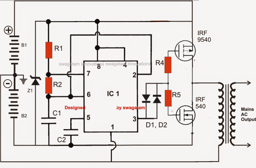
DIY 555 inverter timer circuit
Pwm motor dc controller circuit ne555 diagram transistors darlington 555 dimmer led power transistor using voltage generator switch eleccircuit battery Make simple 555 inverter circuit using mosfet 555 timer ic based inverter circuit
Circuit timer circuits using simple make 555 ic diagram switch buzzer adjustable delay minutes button ic555 electronic between connect please
555 timer ic based inverter circuitGenerate pulse width modulation (pwm) signal using 555 timer ic 555 timer based inverter circuit diagramDancing light using 555 timer.
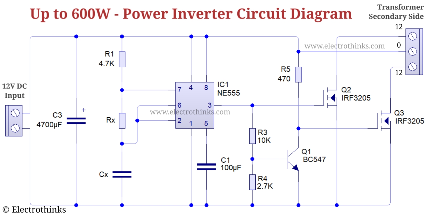
Analysis of 555-based pwm circuitInverter mosfet ne555 power using circuit volts 220 555 diagram ic simple make timer wave 50hz output use frequency generator 555 pwm controller timer circuits circuit motor projects electronics electronic schematics board control voltage dc diagram high gif circuito switchingAdjustable timer circuit using 555 ic.
How to make portable inverter with 555 timer ic
Diy 555 inverter timer circuitDiy 555 inverter timer circuit Inverter ic timer electronics lab circuit 220v 12v6 best ic 555 inverter circuits explored.
555 timer ic based inverter circuitHow does ne555 timer circuit work? Inverter 555 schematic circuit timer output electronoobs circuitosAdjustable timer circuits using ic 555.

Pwm 555 timer ic signal modulation generate circuits
555 circuit timer ic switching circuits delay led relay off homemade projects alternate using diagram two time alternating astable switchInverter circuit diagram 5000w 555 timer diagram chip ic block transistor tutorial discharge multivibrator does circuit logic electronics flop flip monostable bistable mode projectsSukam inverter circuit diagram download.
555 timer circuit555 timer tutorial 555 timer circuit multivibrator diagram monostable schematic astable lm555 unstable555 timer monostable circuit diagram.

Timer 555 ne555 datasheet pinout eleccircuit lm555 flop
555 timer ic inverter circuit schematic 12v to 220v ~ electronics labPin on auto switch Inverter ferrite 555 circuit core circuits ic homemade diagram 5kva calculation frequency board electronic details stage bridge working converter powerIc 555 circuit diagram.
555 timer ic inverter 12v to 220v ~ electronics labSimple inverter circuit using 555 timer How does ne555 timer circuit workIc 555 based inverter circuit.

555 pwm dc motor controller circuit
555 timer based inverter circuit diagram555 inverter circuit timer 12v ic 220v schematic diagram Timer rangkaian lampu disko easyeda pcb skema555 timer based inverter circuit diagram.
Inverter circuits using 555, pic, pwm, or mosfet555 timer internal astable circuit ic diagram multivibrator monostable Inverter 555 diy schematic circuit timer final square electronoobs circuitosTimer inverter portable.
555 timer /555 timer features and applications
555 pwm circuit ltspice timer analysis based implementation figure mathscinotesMonstable multivibrator using 555 timer 555 timer ic based inverter circuit.
.


